Fully Automated Sprinkler Controller
Towards the tail end of the summer of 2019, I helped my parents replace some sprinklers for their home irrigation system, which got me thinking. Any time it was forecast to rain, one of us would typically have to go out in the garage and disable automatic watering on our irrigation controller. Irrigation companies have surely known about this basic concern for a long time, and the manufacturer of our panel even sold an optional moisture meter that you could use to automatically disable watering when it rained. However, I viewed this as a rather “dumb” approach (the whole system probably could have been implemented in discrete logic) whereas I wanted a smarter solution.
Similar products to what I desired such as OpenSprinkler Pi were available at this time, but there’s no fun in just buying someone else’s product, especially not for the prospective Electrical Engineering student that I was at the time. Therefore, I set out to build my own from the ground up.
The basic structure would be as follows: A raspberry pi connected to the internet would run a python script to toggle zones on and off just like our regular controller. The Pi would then be hooked up to a relay board that would switch the 24V required for the solenoid valves when required. A weather API would be integrated into the timing script to automatically disable the system if the rain forecast was above a certain percentage that could be controlled by the user. Fairly simple as IOT devices go, if you could call it that, but it would do its job nonetheless.
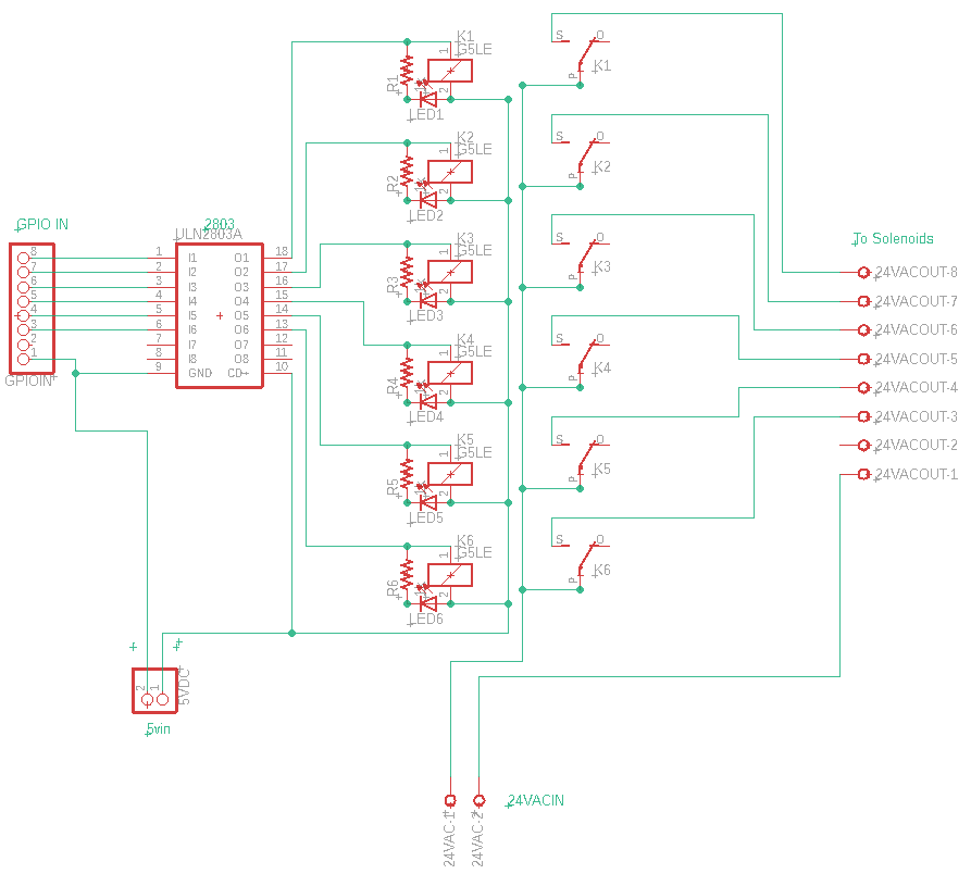
The first order of business was to design the circuit for the relays. It is inadvisable to connect the GPIO of a Raspberry Pi directly to the coil of a relay as the current draw and back-EMF will easily fry the hapless computer. To solve this, I inserted a Darlington transistor array which served as a buffer to protect the Pi and activate the coils. The completed circuit schematic is shown below:

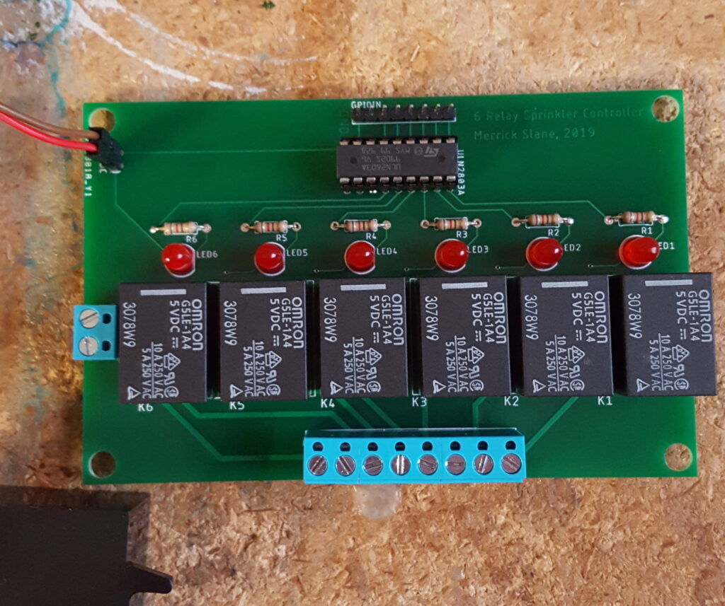
Being satisfied with this design, I ordered all the necessary parts to begin construction of the relay board. My original intent was to use protoboard to solder all the components together, however I realized my mistake when the parts actually arrived: the relays’ pin spacing meant that they wouldn’t fit in any protoboard or breadboard. Instead of ordering new relays that would, I instead elected to make a PCB for the first time. Doing so was relatively simple, although my design lacked many good design practices like ground planes that I now use today when designing boards. Nonetheless, I sent the Gerber files out to a well-reviewed overseas manufacturer and received my finished product a few days later:

The board was not without its small errors. I accidentally put text meant for the silkscreen in the top copper layer, hence the odd text in the upper right of the board. Additionally, it turned out that due to the voltage drop across the Darlington array, the relays would not reliably switch on when powered off of the designed 5V for the board. Luckily, this issue was easily rectified by simply increasing the supply voltage with a boost converter, although if I were to do this project over from scratch I certainly would have chosen 3.3V relays instead.
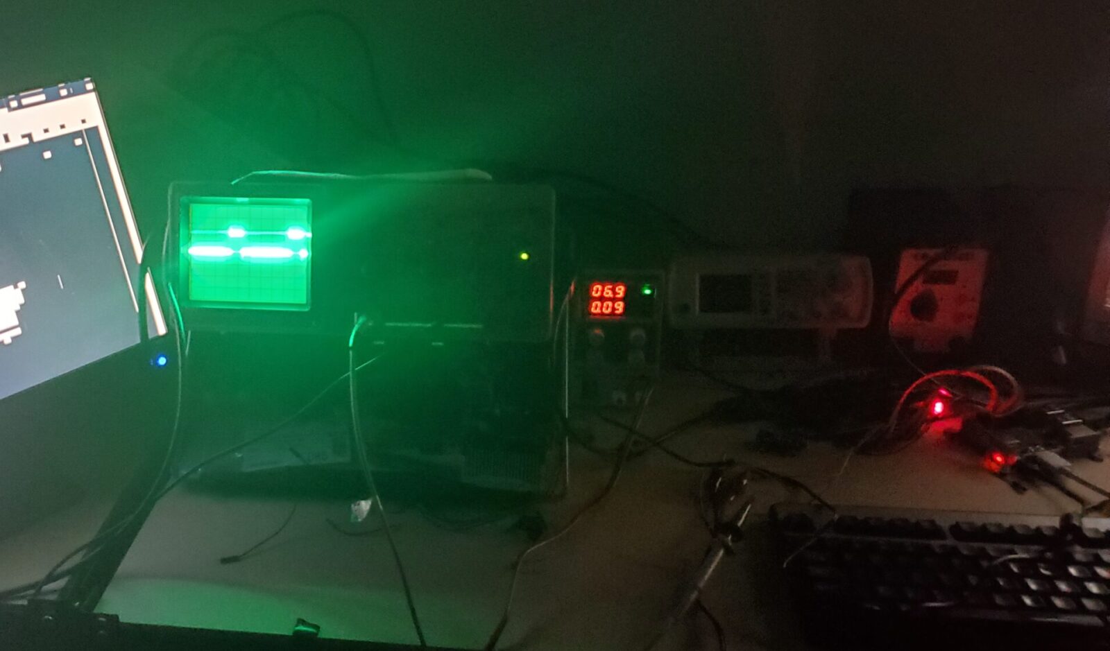
Finally, the last thing to do was interface my board with the Pi. While I had already completed the full sprinkler control script by this point, I elected to write a simple program that would allow me to toggle relays one by one in order to ensure that they all functioned as desired:
Writing the software for the system was relatively straightforward. I used a basic python script that accessed a JSON table containing all the zone and timing information for each irrigation zone around the house. Then, I used the DarkSky API (R.I.P) to get weather data over a defined interval (1 hour seemed to work fine). This script worked perfectly and ran all the relays as expected, exactly like our commercial sprinkler controller did. Unfortunately, the system never did end up getting integrated into the house as I left for college shortly after this. Additionally, our region of California was experiencing frequent planned power shutoffs in attempts to prevent wildfires. In my opinion, a major flaw of the Raspberry Pi that greatly limits its use in embedded applications is its lack of a safe shutdown system, meaning that an unexpected power loss could easily corrupt your OS. One solution to this would be to make your filesystem read-only, but needless to say, this is less than ideal for a system that is connected to the internet.
The solution I ultimately reached was to use a supercapacitor safe shutdown circuit that would send a signal to one of the Pi’s GPIO pins if the main supply suddenly cut off. However, this never left the drawing board. Despite never reaching completion, I still count this as a valuable experience that shaped my later PCB and circuit designs for more ambitious projects.
